Flutter Analysis
Blade flutter is the self-excited vibration of blades due to the interaction of structural-dynamic and aerodynamic forces. It is a significant problem for the manufacturers of large-scale turbomachinery such as gas turbines, steam turbines and aircraft engines. It can lead to dramatic blade loss in the short-term and high-cycle fatigue (HCF) in the long-term.
Flutter is a problem for turbomachinery because of the possible phase differences between the blades when they are vibrating. If the blades are identical, the aeroelastic modes (coupled structural and aerodynamic system) are patterns of blade vibration with a constant phase angle between adjacent blades. Each aeroelastic mode has a different inter-blade phase angle. The inter-blade phase angle affects the phase between the local unsteady flow and local blade motion which in turn affects the unsteady aerodynamic work done on the blades. Adverse phase angles can lead to positive work being performed on the blades which results in flutter.
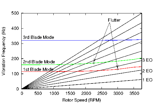
Flutter can be identified as the cause of blade vibration by examining the frequency of the vibration. If the frequency is very close to a blade mode frequency and is not near an engine order frequency then the vibration is probably due to flutter. This can be shown graphically in a Campbell diagram (see below). Turbomachinery flutter occurs at frequencies very close to a blade mode frequency because the structural forces dominate and the aerodynamic forces do not significantly affect the vibration frequency.
In order to evaluate the flutter risk, it is necessary to determine the unsteady flow due to the blade mode shape for each possible inter-blade phase angle. The blade mode shapes can be determined by standard FE analysis and the aerodynamic forces can be neglected. The calculated unsteady aerodynamic work is used to calculate the logarithmic decrement (log-dec) of the blade motion for each aeroelastic mode. The log-dec is the rate of decrease in the blade vibration amplitude per cycle. Negative log-dec values indicate growth in the blade amplitude and a possible flutter problem if there is insufficient mechanical damping.
Unsteady Flow Modelling
The most difficult and computationally expensive component of flutter prediction is the determination of unsteady aerodynamic forces. Flutter usually occurs at off-design operating conditions where flow separation occurs, for example, stall flutter and choke flutter. 3D viscous flow modelling is necessary to accurately predict separated flow. In the past, 3D unsteady viscous flow modelling has been too computationally expensive to use during the design phase. Manufacturers have had to rely on simplified flow models (e.g. 2D inviscid), reduced order models and empirical data during the design process. It has been shown that simplified models and empirical data fail to capture the physics of unsteady flow, and hence have a limited range of applicability. However, due to the continuing development of numerical methods and the constant increase in the speed and memory of computer hardware, it is now possible to perform 3D viscous flutter analysis during the design phase.
Linear Flow Analysis
While other unsteady flow frequencies may exist in the flow, only the unsteady flow component at the structural frequency contributes to the work that feeds flutter. Linear flow analysis can be used to accurately predict the unsteady flow at the blade mode frequency. The unsteady flow perturbations are assumed to be small and the unsteady flow response is assumed to be linear. This assumption is valid for many flutter cases in turbomachines. Linear flow analysis is 10 to 100 times faster than conventional time domain methods and just as accurate for most cases.
3D Viscous Flutter Analysis
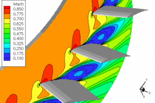
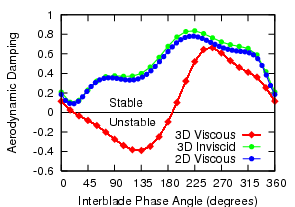
Below is an example of a 3D viscous flutter analysis of a compressor blade. The plot on the right shows the aerodynamic damping for a blade torsion mode for various flow models: 2D viscous, 3D inviscid and 3D viscous. The results of the 3D viscous analysis are significantly different from the 3D inviscid and 2D viscous analyses with the 3D viscous model predicting some unstable cases while the other flow models predict that all cases are stable. The reason for the difference is the presence of corner separation near the hub and suction surface of the blade. The corner separation can be seen in the figure below (left) of a contour slice of flow Mach number at ten percent blade height. The corner separation is only captured by the 3D viscous simulations. This highlights the importance of 3D viscous effects on flutter.


Economic Benefits of Flutter Analysis
Early identification of potential flutter problems can have significant economic benefits:
- reduction in development and design costs
- reduction in losses due to development delays
- reduction in maintenance costs
- 3D Navier-Stokes flow modelling
- Full turbulence modelling
- Exact 3D non-reflecting boundary condition
- An efficient and robust solver: unsteady 3D viscous simulation (450 000 cells) in 20 minutes
It has been estimated that 30 percent of overall development costs of jet engines is due to high-cycle fatigue (HCF) management and that each new jet engine development has on average 2.5 HCF problems, which lead to considerable time delays and cost overruns. The occurrence of flutter can also cause delays in development of steam turbines. Delays in development for a medium-size 500 MW power plant can lead to a loss of revenue up to 2.5 million US dollars per week.
RPMTurbo Services
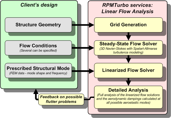
The flutter analysis process as performed by RPMTurbo is shown below. A customer has a preliminary design (turbomachinery blade) and wishes to know the flutter risk of various blade mode shapes at various operating conditions.

RPMTurbo has developed a 3D linearized Navier-Stokes flow solver to calculate the unsteady flow response due to blade motion. The main features of RPMTurbo's linearized flow solver are:
To perform the calculations, RPMTurbo uses a 180 dual-processor AMD Opteron distributed parallel computing cluster with 720Gb of distributed memory.
Design Impact
Previously, 3D unsteady viscous flow simulations were only performed for research purposes. RPMTurbo has developed a linearized flow solver that is capable of performing a 3D viscous unsteady flow simulation in 20 minutes. RPMTurbo can complete a full 3D viscous flutter analysis involving hundreds and even thousands of unsteady flow simulations in a short time-frame (weeks not months) that is acceptable to the design engineer. As a result, 3D viscous flutter analysis can play a role in the design process and result in a significant economic benefit for manufacturers due to reduced development costs and reduced losses due to development delays.
Complex Blade Mode Shapes
The mode shapes of turbomachinery blades that have significant structural coupling (flexible disk, shrouded blades, and/or blades tied together) can be complex. RPMTurbo's linearized flow solver can determine the unsteady flow response due to complex mode shapes.
