Unsteady Waves in Multi-Row Turbomachines
Many turbomachinery applications have multiple stages. However, for acoustic and forced response problems, it is usual to assume that the source of unsteady flow is just from the wake of the upstream blade-row. Also, for flutter problems it is usual to assume that the unsteady flow is due to the motion of an isolated blade-row. In reality, unsteady waves are reflected from adjacent rows and also transmitted from blade rows further up or down stream. These reflected and transmitted unsteady waves in multi-row turbomachinery can affect the flutter, acoustic, or forced response behavior of a blade row.
Multi-Row Wave Plot
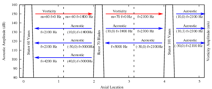
An example of a multi-row wave plot for a stator-rotor-stator combination is shown below. It is assumed that the rotor has a frequency of 30 Hz. Some of the possible acoustic modes generated by the interaction of the first harmonic of the wake (vorticity waves) from the upstream stator and rotor are shown. Sometimes higher harmonic vorticity waves can also be significant but they are not shown here. Also not shown are transmitted and scattered vorticity waves. The dashed lines represent the interfaces between the rows and the frequencies shown are relative to the row.

The plot shows how unsteady waves with different frequencies and from different sources can act on a blade row in a multi-row turbomachine. It is often important to consider these multi-row effects in order to predict the flutter, acoustic, or forced response behavior of a blade row.
RPMTurbo Multi-Row Analysis
RPMTurbo can perform a multi-row unsteady wave analysis. Linearised flow simulations are performed for each separate frequency. The unsteady waves at the inlet and outlet are transmitted to adjacent rows and new linearized flow simulations for adjacent rows are performed at the correct frequency. One important feature of RPMTurbo's multi-row analysis is the application of an exact three-dimensional non-reflecting boundary condition. This boundary condition ensures that the correct amplitude and phase of each mode is transmitted to the adjacent rows. The boundary condition also prevents non-physical reflections at the inlet and outlet which can reduce the accuracy of the linearized flow simulations. The boundary condition is also important for determining the correct amplitude and shape of the incoming vorticity and acoustic (potential) modes.