2D Steam Turbine Flutter Test Case
RPMTurbo has developed a 2D steam turbine flutter test case. The geometry and flow conditions are similar to those of a typical industrial steam turbine near the tip. The tip region is critical for flutter analysis because this is where most of the unsteady aerodynamic work that drives flutter occurs. The test case has the following features that differ from other standard 2D flutter test cases:
Problem Description
The geometry is a 2D cascade of flat plates with half circles at the leading and trailing edge and a high stagger angle (78 degrees). The isentropic Mach number at the turbine exit is high (1.362). A complete description of the geometry and the flow conditions for the test case are given in the tables below.
|
|
| ||||||||||||||||||||||||||
The flow is assumed to be viscous and the ideal steam properties chosen for this test case are shown in the table below. The aim of the test case is to calculate the flutter stability (aerodynamic damping) due to a blade vibrational mode with motion normal to the blade (similar to a 3D bending mode). The description of the vibrational mode is given in the table below.
|
| ||||||||||||||||
Mesh
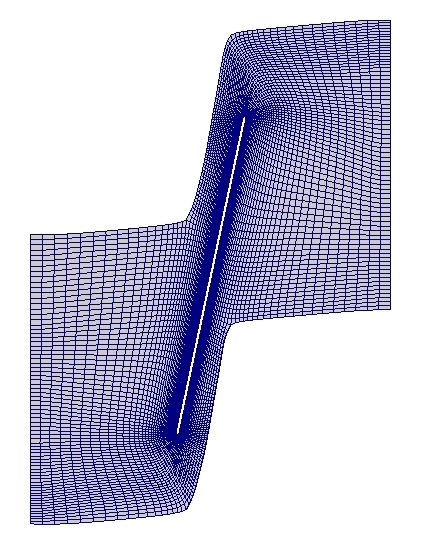
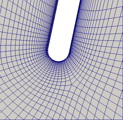
RPMTurbo has created three multi-block meshes for this test case. The long and short domains have the inlet and outlet planes at different locations. The details of the meshes are shown in the table below. Each mesh has an O mesh around the profile. The long domain mesh is shown in the figures below. There are links to download the meshes in the table below. The meshes are stored in cgns files as unstructured meshes of hexahedral cells.| Mesh | Long Domian | Short Domain | Fine Mesh |
|---|---|---|---|
| Number of cells | 10285 | 9829 | 39932 |
| Min mesh angle (degrees) | 42.24 | 39.86 | 37.83 |
| Average height of first cell on profile (m) | 1.76e-5 | 1.74e-5 | 1.2e-5 |
| Centre of half circle at leading edge (m) | (0.0, 0.0) | (0.0, 0.0) | (0.0, 0.0) |
| Centre of half circle at trailing edge (m) | (0.045741, 0.215192) | (0.045741, 0.215192) | (0.045741, 0.215192) |
| Axial location of inlet (m) | -0.100 | -0.0500 | -0.100 |
| Axial location of outlet (m) | 0.1457 | 0.1000 | 0.1457 |
| CGNS file | longDomain.cgns (1.79 Mb) | shortDomain.cgns (1.71 Mb) |
Steady-State Solutions
Steady-state solutions for this test case were calculated by RPMTurbo's LUFT code. The flow model was the Reynolds-averaged Navier-Stokes equations with the Spalart and Allmaras Turbulence model. The flow was assumed to be fully turbulent with the incoming Spalart and Allmaras turbulence variable set to 0.1. This corresponds to an incoming turbulent intensity equal to 4.52%. Details of the steady-state solution calculated on the long domain are shown in the table below.
| Inlet Mach Number | 0.699 |
|---|---|
| Outlet Mach number | 1.312 |
| Reynolds number (based on outlet conditions) | 664 183 |
| Average y+ on profile | 1.20 |
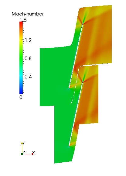
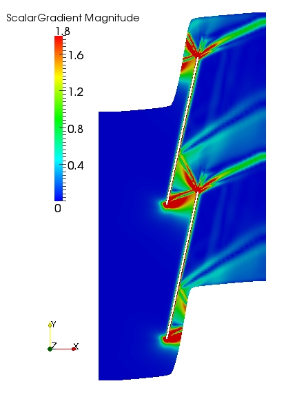
The steady-state Mach number of the flow-field calculated on the long and short domain meshes are shown below (left). The flow-fields are similar for both domains and the steady-state solution is independent of the far-field location. Also, there is no evidence of reflections of the steady waves at the inlet and outlet of the domain from the numerical schlieren plot (magnitude of density gradient) shown below (right).
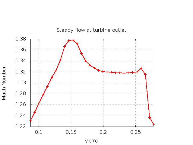
One characteristic of this test case is that the steady flow at the outlet is not uniform. The variation in the Mach number in the pitch-wise direction can be seen in the plot below.
Unsteady Flow Solutions
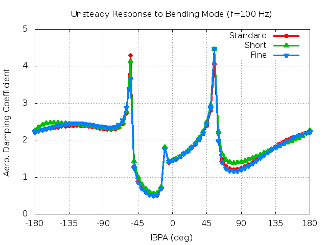
The flutter analysis is performed by calculating the unsteady flow response due to the blade vibrating at the prescribed mode shape at various interblade phase angles (IBPA). The IBPA is the constant difference in the phase angle of the blade motion between adjacent blades. It is necessary to calculate the unsteady flow response at all possible interblade phase angles, in order to consider the effects of the aerodynamic and structure coupling between the blades. The aerodynamic damping is the non-dimensional damping work done by the aerodynamics on the blade motion. If the aerodynamic damping is negative, then there is a potential flutter problem.
The aerodynamic damping calculated by the RPMTurbo LUFT code for this test case is shown below. RPMTurbo's 3D non-reflecting boundary condition (3D-NRBC) was applied at the inlet and outlet. The solutions were calculated on the short, long and fine meshes. The aerodynamic damping calculated on the three meshes agree well. This demonstrates that the solutions are independent of the mesh resolution and location of the inlet and the outlet.
